
Documentation
Modelling
Valos Framer is a true 3D BIM (Building Information Modelling) application. All modelling is done in 3D. All documents, like drawings, are produced automatically with the possibility to add manual content. The storage format is a SQL-database and the schema of the database and the model is freely expandable keeping the compatibility backward and forward. The model is arranged hierarchically and hence each model object has a parent. The user can arrange the model freely by defining the hierarchical tree of the whole model. In addition to the free hierarchy, there is a fixed hierarchy for model objects and components that have a constant parent-child relation. The model hierarchy can be seen in the Model Explorer window. The hierarchical model arrangement makes up an unlimited number of partial models whose visibility can be controlled by lamps in the Model Explorer window.
Point input
Whenever point input is required the point input tool is shown after the first point is selected. The point input tool displays the direct distance between the previous and current points and the X-, Y- and Z- (if the current point is off the 0-plane) components relative to the current UCS-grid. Whenever the tool is visible the Tab-key may be used to cycle between the different components to lock them to desired values. Backspace- and Del-keys may be used to remove the locks. O-key may be used to lock the angle component to the original direction. The P-key may be used to lock the angle component to the perpendicular direction. The R-key (relative input) allows you to select a new start point for the point input tool without affecting the active modelling command.
Snapping of point input can be controlled from the Model View tab of the application. The different snap options can also be toggled using the numeric keys 1-6.
Point input is always done relative to an active UCS-grid. Multiple UCS-grids may be inserted into the model depending on the modeling needs, but only one may be active for the point input tool at a time. Select the desired grid from the Model Explorer, right-click and select “Set as Current Grid”. The point input tool displays its components relative to the active grid.
Walls
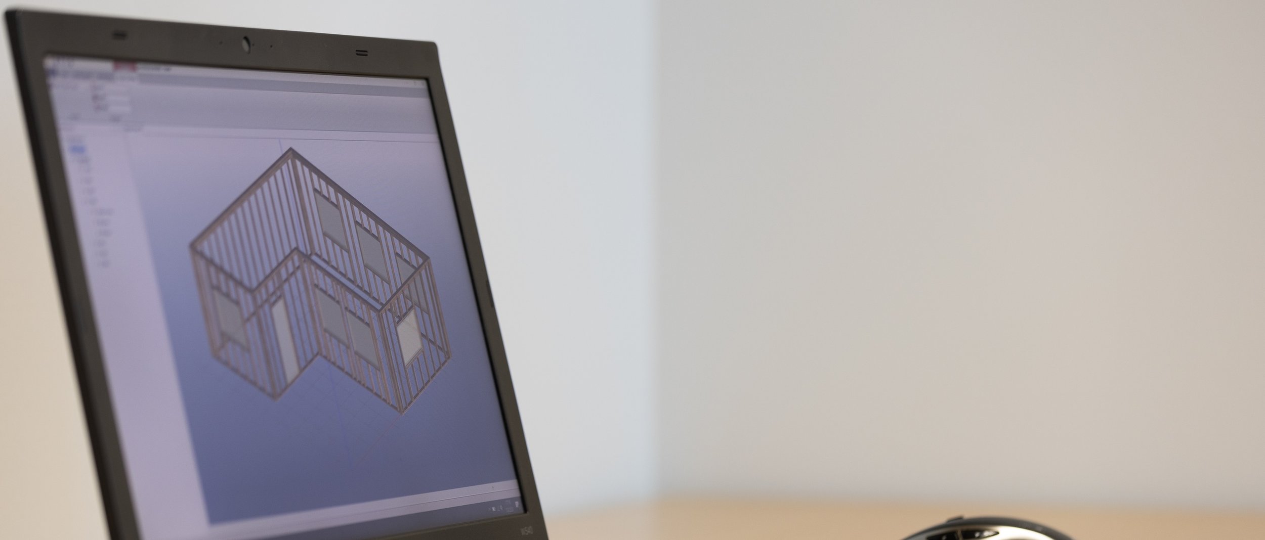
Walls with timber studs can be modelled. Wall can be created as a polygon or one by one. The tool for the wall modelling can be found from Tools ribbon of the building. Select a building from the tree window, activate Tools ribbon and the wall modeling can be started. Edit for an existing wall is found by selecting the wall and clicking the Edit button on the ribbon.
It is possible to model walls that have more layers, but only a layer of timber members is fully supported at first. There are some predefined walls that can be selected (Wall from library), “Only studs” is a wall having a single layer of timber members. For each layer of the wall, the type of the layer can be selected. Currently only “Vertical stud work” is supported fully. Trial marked walls and wall layers can be used, but full support for trials is coming to next versions. Properties for the wall and wall layer are:
· Wall shape: An even height or gable wall can be selected.
· Wall height: The height of the wall and the default height for layers of the wall.
· Thickness: The layer thickness
· Offset bottom/top: The layer offset at top and bottom. Changes the start and end of the layer in the height direction.
· Timber spacing: The spacing of vertical timber studs.
· Timber cut length: The maximum length for timber members.
· Double top plate. An option to make the topmost horizontal timber as double.
· Top plate is support: An option to make the top plate as a 3DTrussMe support.
· Add 90 degrees rotated stud at start/end: An option to add an additional vertical stud rotated 90 degrees along the vertical to the start/end.
· Header beam at top: An option to add an additional beam below the top plate.
· Add walls connector: An option to add connector between walls.
The wall can be moved with an option to move connected walls also. This feature requires that the walls have connectors and are in right angle. Also wall must be moved perpendicular from the middle.
Modelling window, door or opening
A window, door or opening can be added to the wall. Timber members of the wall are automatically repositioned. Properties for window/door/opening are:
· Horizontal/Vertical distance from wall start/bottom: Distances are measured from the wall start point; the position can also be changed using the mouse.
· Offset from wall inner side: Moves the window or door in the thickness direction of the wall.
· Frame depth: Size of the frame of the window/door in the wall depth direction.
· Clearance: Gap between the window/door frame and the timber member of the wall.
· Restart framing spacing left/right: Option to continue or restart the spacing of vertical studs at left/right of the window/door/opening.
· Double stud left/right: Option to make double studs at left/right of the window/door/opening.
· Header beam at top: Option to add an extra beam above the window/door/opening.
Modelling member
Timber members can be modelled under the building or wall. Under a wall, the member has an option “Cuts other parts”. When set on, a member will cut all other members in the same layer of the wall. Typically, a header beam cuts other members in the same layer.
Selection of objects
Objects and components can be selected from the hierarchical tree view of the model or from the 3D model. A wall component is made up of child components, a wall node itself has no geometrical representation. Due that, a wall can be selected from the 3D model by pressing a key “W” on the keyboard along with the mouse.
Valos Framer uses contextual ribbon menu. Based on the selection, the context of the ribbon changes. Only commands that are valid for the current selection are available in the ribbon menu.
Drawings
The basic handling of drawings and blocks of the drawing is like in 3DTrussMe. A drawing can be added to a wall and the add command can be found from the tools ribbon of the wall. After the drawing has been added, it can be opened from the tree view. By default, the drawing is empty and has only one page. An unlimited number of pages can be added, and each page can be sized individually. For each page, blocks can be placed and sized freely. Available blocks can be found from the ribbon of the drawing page, selecting the page activates the ribbon of the drawing page. Each block has its own ribbon and by selecting the block, properties and tools for that block are available in the ribbon.
Face view block
A face view block for a wall can be added. Automatic dimensions and labels can be generated and controlled with various settings. Also, visibility of wall parts can be controlled even at the single member level. The generation of the automatic content can be set off with an option to leave or remove. In addition, manual lines, dimension lines and labels can be added to the face view block.
Stick list for timber members of the wall
A graphical stick list showing the geometry, main dimensions and properties is available.
Text block
A text block containing formatted text can be added on a page of the drawing. The text can be written and formatted, for example in Word, and then copy-pasted into the block. The text block itself has no text formatting tools.
3D view block
A 3D view for which the view position can be freely set.
Image block
An image can be added on the drawing page
Parts list
A bill of quantities list of the wall
Title block
A title block for the drawing. Title blocks are defined as xml-files and new ones can be added. Variables enclosed between square brackets [ ] can be used both in the title and text block.